Drilling is an operation through which holes are produced in a metallic or non-metallic material through a revolving tool called a drill. The whole process is carried out on a specific machine known as a drilling machine. The machine provides rotatory motion to the drill and is directed toward the workpiece where the hole is to be made.
The drilling tool makes contact with the workpiece and pressure is applied to it along with the rotatory motion of the drill. The hole can be made with the help of a lathe machine but the lathe does not provide us variation in the hole in terms of shape and size. So, the requirement for a drilling machine to make a hole is increased. The drilling machine provides a wide range of drilling and its different drilling tools are used to make the different types of holes. In this chapter, we will discuss the drilling machine, its tools, and drilling operations.
Drill
The drill is a tool having two cutting points and making a hole in the solid materials. It is made up of high-carbon steel or alloy steel. Drilling is the term applied to the process of originating a hole in a solid metal workpiece using a drill. It is a bench work operation. The high accuracy of a hole cannot be made by drilling.
For drilling, the drill is rotated with a downward press, which causes the tool to penetrate the material. According to the shape and size of a hole, there are many types of drill, which are as follows.
Flat Drill
The flat drill is usually made up of high carbon steel, which is forged to shape and ground to size, then hardened and tempered. It is a simple type of drill and has two cutting edges beveled at 45°.
The disadvantage of this type of drill is that each time the drill will be grounded and the diameter is reduced. It cannot be used to drill deep holes because the chips do not come out from the hole during the operation.
2. Straight Fluted Drill
This is used for rough drilling and has two straight flutes cut, which is made up of high-carbon steel. It is hard, tempered, and works as a twisted drill. Its only disadvantage is that the chips pack in the flutes.
3. Twist Drill
It is the most commonly used variety of a drill and is made with two, three, or four cutting lips. The main advantage of these flutes is their chips come out easily and coolant reaches to cutting point easily.
It is made up of high-carbon steel. It has a taper or parallel shank.
The parts of a twist drill are discussed below.
(i) Body
It is made up of cast iron steel. It has a flute cut, which is used for cutting the workpiece. It contains the following parts.
(a) Flutes
It is spiral grooves in the drill body. These are marked by milling and cutting on a flute rod.
(b) Land
A wider part between two flutes on a body is known as land.
(c) Margin
A thin raised line adjacent to the edges of the flutes, which are polished the hole from the inside. This part comes in contact with the hole. It measures the size of a drill.
(d) Body Clearance
It is a wide area behind the margin, where the diameter of a drill is less known as body clearance.
(e) Web
The width between two flutes on a line of the axis is called a web. Its width increases toward the shank, increasing the strength of a drill.
(f) Chisel Point
It is a conical surface below the body of a drill. It is also called the dead center.
(g) Cutting Lips
A number of flutes are known as the cutting lips. The angle of the drill lip and rake depends upon the metal and ground accordingly to different degrees. It is also called cutting edge.
(ii) Shank
It is the driving end of the drill, which is fitted on the machine with the spindle or a tool-holding device. There are mainly two types of shank, which are as follows.
(a) Straight Shank
It contains less than 13 mm drill size. It is mostly used for holding it in a drill holder socket.
(b) Taper Shank
It is used for drilling the big size hole. It has more taper and is easily fitted into the drill machine. In the drilling process, it has more pressure, so it can be used for drilling a hole of a big size in a short time period.
(iii) Neck
It has a small surface area between the body and the shank. It marks the drill size and company name on the space. diameter is slightly smaller than the size of a drill.
(iv) Flutes
The spiral grooves, which run to the length of a drill are known as flutes. It is marked by milling, and cutting on a flute rod.
(v) Land
It is a narrow strip, which extends to the entire length of the flutes.
(vi) Margin
The diameter of the drill is measured across the land. It is a thin raised shining adjacent edge of flutes that polished the hole from the inside because this part comes in contact with the hole.
(vii) Body Clearance
It is a part of the body, that is reduced in diameter to cut down, the friction between the drill and the hole being drilled. It has a wider area behind the margin with a small drill diameter.
(viii) Point
It is the front part of a drill, which has a cone shape. It is also known as a chisel edge or dead center. Two important kinds of factors that are related to the point are given below.
(a) Point Angle
It is a cutting angle of the drill of 59° from one side and 59° from the second side i.e., 118° for the general purpose. For special purposes, it can be changed depending upon the drill for the soft metal cutting angle is less than 118°, and for the hard metal is more than 118°. It varies from 80° to 140° according to the working.
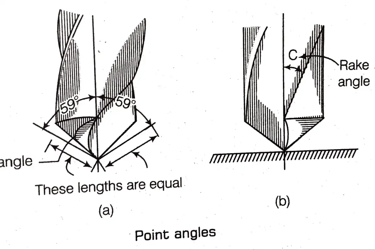
(b) Chisel Edge Angle
An angle between the cutting lip and the chisel edge is known as the chisel edge angle. It varies from 120° to 135° due to the requirements of the operation. It affects the thickness of the angle web. So, it is also called a web angle. The figures of the chisel edge angle are shown below.
Size Confirmation of Twist Drill
There are four tricks to specify a drill size, which are as follows.
(i) Millimetre Size Drill
According to the Metric system, the drill sizes are up to 16 mm in the form of a straight shank and above 16 mm in the form of a tapered shank.
(a) For Straight Shank Drill
| SL NO | Size(mm) | Difference (mm) |
| 01 | 0.2 – 0.98 | Total 32 drill |
| 02 | 1.0 – 3.0 | 0.05 |
| 03 | 3.0 – 14 | 0.1 |
| 04 | 14 – 16 | 0.25 |
(b) For Tapper Shank Drill
SL NO | Size(mm) | Difference (mm) |
| 01 | 3.0 – 14 | 0.3 |
| 02 | 14 – 32 | 0.25 |
| 03 | 32 – 51 | 0.5 |
| 04 | 52 – 102 | 1.0 |
(ii) Number Size Drill
According to the number system, there are available 1 – 80 drills. 1 number drill is the biggest drill number and 80 is the lowest drill number.
Number Size Drill
| SL. NO | Inch | mm | SL. NO | Inch | mm | SL. NO | Inch | mm |
| 01 | 0.228 | 5.791 | 28 | 0.1405 | 3.569 | 55 | 0.052 | 1.321 |
| 02 | 0.221 | 5.613 | 29 | 0.136 | 3.454 | 56 | 0.0465 | 1.181 |
| 03 | 0.213 | 5.410 | 30 | 0.1285 | 3.264 | 57 | 0.043 | 1.092 |
| 04 | 0.209 | 5.309 | 31 | 0.120 | 3.048 | 58 | 0.042 | 1.067 |
| 05 | 0.2055 | 5.220 | 32 | 0.116 | 2.946 | 59 | 0.041 | 1.041 |
| 06 | 0.204 | 5.182 | 33 | 0.113 | 2.870 | 60 | 0.40 | 1.016 |
| 07 | 0.201 | 5.105 | 34 | 0.111 | 2.819 | 61 | 0.0390 | 1.00 |
| 08 | 0.199 | 5.055 | 35 | 0.110 | 2.794 | 62 | 0.0380 | 0.98 |
| 09 | 0.196 | 4.978 | 36 | 0.1065 | 2.705 | 63 | 0.0370 | 0.95 |
| 10 | 0.1935 | 4.915 | 37 | 0.104 | 2.642 | 64 | 0.0360 | 0.92 |
| 11 | 0.191 | 4.851 | 38 | 0.1015 | 2.578 | 65 | 0.0350 | 0.90 |
| 12 | 0.189 | 4.801 | 39 | 0.0995 | 2.527 | 66 | 0.033 | 0.85 |
| 13 | 0.185 | 4.699 | 40 | 0.098 | 2.489 | 67 | 0.32 | 0.82 |
| 14 | 0.182 | 4.623 | 41 | 0.096 | 2.438 | 68 | 0.031 | 0.79 |
| 15 | 0.180 | 4.572 | 42 | 0.0935 | 2.375 | 69 | 0.0292 | 0.75 |
| 16 | 0.177 | 4.496 | 43 | 0.089 | 2.261 | 70 | 0.0280 | 0.78 |
| 17 | 0.173 | 4.394 | 44 | 0.086 | 2.184 | 71 | 0.0260 | 0.65 |
| 18 | 0.1695 | 4.305 | 45 | 0.082 | 2.083 | 72 | 0.0240 | 0.65 |
| 19 | 0.166 | 4.216 | 46 | 0.081 | 2.057 | 73 | 0.0240 | 0.60 |
| 20 | 0.161 | 4.216 | 47 | 0.0785 | 1.994 | 74 | 0.0225 | 0.58 |
| 21 | 0.159 | 4.039 | 48 | 0.076 | 1.930 | 75 | 0.0210 | 0.52 |
| 22 | 0.157 | 3.988 | 49 | 0.073 | 1.854 | 76 | 0.0200 | 0.50 |
| 23 | 0.154 | 3.912 | 50 | 0.070 | 1.778 | 77 | 0.0180 | 0.45 |
| 24 | 0.152 | 3.861 | 51 | 0.067 | 1.702 | 78 | 0.0160 | 0.40 |
| 25 | 0.1495 | 3.797 | 52 | 0.0635 | 1.613 | 79 | 0.0145 | 0.38 |
| 26 | 0.147 | 3.734 | 53 | 0.0595 | 1.511 | 80 | 0.0135 | 0.35 |
| 27 | 0.144 | 3.658 | 54 | 0.055 | 1.395 |
(iii) Letter Size Drill
In the letter size drill, there are numbers having English alphabets from A to Z. In letter size drill, A represents the smallest size of a drill i.e., diameter 0.234″ or 5.994 mm and Z is the biggest size of a drill i.e., diameter 0.413″ or 10.490 mm.
Letter Size Drill
| SL NO | Inch | mm |
| A | 0.234 | 5.944 |
| B | 0.238 | 6.045 |
| C | 0.242 | 6.147 |
| D | 0.246 | 6.248 |
| E | 0.250 | 6.35 |
| F | 0.257 | 6.528 |
| G | 0.261 | 6.629 |
| H | 0.266 | 6.756 |
| I | 0.272 | 6.909 |
| J | 0.277 | 7.036 |
| K | 0.281 | 7.137 |
| L | 0.290 | 7.366 |
| M | 0.295 | 7.493 |
| N | 0.302 | 7.671 |
| O | 0.316 | 7.026 |
| P | 0.323 | 8.204 |
| Q | 0.332 | 8.433 |
| R | 0.339 | 8.611 |
| S | 0.348 | 8.839 |
| T | 0.358 | 9.093 |
| U | 0.368 | 9.347 |
| V | 0.377 | 9.576 |
| W | 0.386 | 9.804 |
| X | 0.397 | 10.084 |
| Y | 0.404 | 10.262 |
| Z | 0.413 | 10.490 |
Types of Twist Drills
According to the shape, twist drill is classified into the following types.
(i) Two Flutes Drill
Generally, a twist drill has two flutes and two cutting cores. It is rigid and is not used for deep holes.
(ii) Multi Flutes Drill
It is used for drilling deep holes because there is a maximum space for chips to exit from the hole. In this, the drill makes the hole well-finished and polished.
Advantages of a Twist Drill
(i) In the twist drill, flutes have a spiral shape. The scrap chips go out from the drill itself.
(ii) It has a long life.
(iii). The cutting-edge lives for a long time. It does not repeat again and again.
(iv) It has a high cutting speed.
(v) It has a simple cooling way of cutting edge.
4. Taper Shank Core Drill
It is similar to the twist drill but it is used for boring. It has a small cutting edge, not filled up to the center so it is not used in a new drill.
5. Oil Hole Drill
It has an oil hole in the shank and body. This provides the oil for the cutting edge. It protects the cutting edge from the heating during the cutting out of the cutting chips. These holes absorb the compressed air or pressure by the oil. It is also called a barrel drill.
6. Centre Drill
It is used for drilling a conical shape on both ends of a job or workpiece at the lathe machine or the milling machine. It can do drilling and counter-sinking at one time. So, it is also called a combination drill.
7. Counter Bore Drill
It is used for drilling and boring operations. It has a fillister head screw. Its shank is straight or more taper with a nozzle of shorter diameter instead of cutting teeth during spot facing in the deep hole. It will not fasten in the hole.
8. Multi-Diameter Drill
Its body has two or three diameters. It has a property to make the different diameters of a hole at a time. It has a drill taper and a straight shank. It is used in step drilling, so that, it is also called step drill.
9. Counter Sink Drill
It is used to change the shape of a hole ie., remove the burs from the counter sink riveting and edges of drill holes. It has a short length of a body with flutes. Its cutting point is ground from 60° to 82° angles.
10. Spirek Drill
It has a special structure i.e., a very slender drill. It has diameters from 0.0086″ to 0.0984″. It is used for making the diesel engine pump, nozzle, and nipples of gas or stove.
Grinding of a Drill
It is a sharp process of cutting edge. For the grinding, the lip angle, length of lip, and lip clearance angle must be equal to the cutting edges.
There are many steps of grinding, which are as follows.
(i) For the sharpness, we can use the side face of a grinding wheel.
(ii) The lip angle is adjusted according to the workpiece.
(iii) According to the figure, having one hand at the front and a second hand at the back on the drill and applying a light force on the drill.
(iv) For the complete cone grinding, the rounding of the backhand with pressure is to be done.
(v) At the grinding time, measure the lip angle. The lip is equal to the length.
Defects of Drill Grinding
Due to the grinding, a cutting edge creates some defects, which are as follows.
Defects of Drill Grinding
| SL NO | Defect of Drill | Defect of Hole |
| 01 | The lip angle and cutting angle both are unbalanced. | Having a big size. |
| 02 | Cutting edges unbalanced. | Increase the friction. |
| 03 | To be less or lost of lip clearances. | Due to less force, the cutting edge will break. |
| 04 | Increase the dead center size. | To apply the high quantity force. |
Cutting Speed and Feed of a Drilling
In the cutting operation, drill rounds on its axis. Its speed depends on its per-minute revolution. It is denoted by revolution per minute e.g., 300 revolutions per minute or 300 rpm.
Cutting Speed
It represents the drill speed of the workpiece diameter. That means a point that moves or rounds at the drill’s diameter in a single minute known as the cutting speed of this drill.
It depends upon the moving speed of the drill and metal of the workpiece but became the limit speed, the tool is blunt with heating. There are many cutting speeds for different metals.
Cutting Speed for Different Metals
| SL NO | Metals | Cutting Speed (m/min) |
| 01 | Alloy steel, stainless steel | 5-8 |
| 02 | Cast iron (white) | 12-18 |
| 03 | Mild steel, carbon steel, malleable iron | 20-30 |
| 04 | Bronze | 20-35 |
| 05 | Cast iron (grey) | 25-40 |
| 06 | Copper, brass | 35-45 |
| 07 | Aluminium and its alloys | 70-100 |
Mathematically, the cutting speed can be found as
Cutting speed = πDN/1000 m/min
where,
D = diameter of drill in mm
N = drill’s revolution. per minute.
If the drill size is in inches, then cutting speed = πDN/1000 ft/min
Where,
D = diameter of a drill in fit
N = drill’s revolution per minute.
Feed
The penetrated distance by a drill into the workpiece in one complete revolution is called feed. It is expressed in hundredths of a millimeter. e.g., 0.040 mm.
The rate of a feed is dependent upon a number of factors that mean rigidity of the machine, holding of the workpiece and the drill will also have to be considered while determining the feed rate. If these do not require standard then the feed rate will have to be decreased. of
It is not possible to suggest a particular feed rate taking all the factors into account. The coarse of a feed may result in damage to the cutting edge or breakage of the drill.
The table for the feed rate is given based on the average feed values suggested by the different manufacturers of the drill.
Feed Rate for Different Drills Diameter
| SL NO | Drill Diameter (mm) | Rate of Feed (mm/rev) |
| 01 | 1.0 – 2.5 | 0.040 – 0.060 |
| 02 | 2.6 – 4.5 | 0.050 – 0.100 |
| 03 | 4.6 – 6.0 | 0.075 – 0.150 |
| 04 | 6.1 – 9.0 | 0.100 – 0.200 |
| 05 | 9.1 – 12.0 | 0.150 – 0.250 |
| 06 | 12.1 – 15.0 | 0.200 – 0.300 |
| 07 | 15.1 – 18.0 | 0.230 – 0.330 |
| 08 | 18.1 – 21.0 | 0.260 – 0.360 |
| 09 | 0.280 – 0.380 | 21.1 – 25.0 |
Mathematically, the feed rate can be found as
Feed= L/TN mm/revolution
where L = traveled distance by drill. If adding the height of the cone, then
Feed= L+B/ T × N
where B = height of a cone.
Example 1. Find out the time duration in drilling five holes in a mild steel sheet that has 20 mm thickness as a drill diameter is 10 mm. The cutting speed is 1.5 m/min and the feed is 0.05 m.
Solution Thickness of sheet, L = 20 mm
Diameter of drill, D = 10 mm
Cutting speed 1.5 m/min
Number of holes = 5
Feed= 0.05 mm
Also
Cutting speed – πDN/1000
⇒ N= 1000 x Cutting speed / πDN
N= 1.5 x 1000 / π x 10 = 150/π rpm
Also
Feed= L+B/T × N (where, B = 0.3)
⇒ 0.05 = 20+0.3 / T × 150/π
⇒ T = 20 + 0.3 / 0.05 × 150/π
= 23 × 22 / 7 7.5
T = 9′.38″
∵ The expanded time in 1 drill = 9′.38″
∴ The expanded time in 5 drills = 5 9′.38″ = 48′.10″
I.e. 48 min 10 s.