In science, industry, and statistics, the accuracy preferred by a management system is the degree of closeness of a measurement. So, such types of instruments are called precision instruments. Some different types of precision measuring instruments are given below.
Precision Measuring Instruments
1. Vernier Caliper
The vernier caliper is a precision measuring instrument. Its measurement accuracy is 0.02 mm. The vernier, dial, and digital calipers directly read the distance with high accuracy and precision. This caliper comprises a calibrated scale with a fixed jaw and another jaw with a pointer, that slides along the scale.
Parts of Vernier Caliper
The vernier caliper has many different parts, which are given below.
(i) Fixed Jaw
Fixed jaw is the part of the beam scale. One jaw is used for taking external measurements and the other for internal measurement.
(ii) Movable Jaw
The movable jaw is the part of the vernier slide. One jaw is used for taking external measurements and the the other for internal measurements.
(iii) Vernier Slide
A vernier slide moves over the beam and can be set in any position by means of a spring-loaded thumb lever.
(iv) Beam
The vernier slide and depth bar attached to it, slide over the beam. The graduations on the beam are called the main scale divisions.
(v) Depth Bar
The depth bar is attached to the vernier slide and used for taking depth measurements.
(vi)Thumb Lever
The thumb lever is a spring-loaded lever, which helps to set the vernier slab in any position on the beam scale.
(vii) Vernier Scale
The vernier scale has the graduation marks on the vernier slide. The divisions of the vernier scale are called vernier divisions.
(viii) Main Scale
Main-scale graduations or divisions are marked on the beam.
Sizes of Vernier Caliper
Vernier calipers are available in sizes 150, 225, 900, and 1200 mm. The selection of the size depends upon the measurement to be taken. Vernier calipers are precision instruments and extreme care should be taken while handling them.
Some of the precautions while using vernier calipers are discussed here.
(a) Never use a vernier caliper for any purpose other than measuring.
(b) Vernier caliper should be used only to measure machined or filled surfaces.
(c) They should never be mixed with any other tools. Clean the instrument after use and store it in a box.
Least Count in Vernier Caliper
The smallest value of a physical quantity, which can be measured with the help of an instrument, is called the least count of the instrument.
Least count:= Least count of the main scale / Number of divisions on the vernier scale
It is 0.02 mm in the metric system and 0.001 inches in the British system.
Determining the Least Count of a Vernier Caliper
In the vernier caliper, the main scale division (9 mm) is divided into 10 equal parts in the vernier scale. i.e.,
One Main Scale Division (MSD) = 1 mm
One Vernier Scale Division (VSD) = 9/10 mm
Least count 1 mm-9/10 mm 1/10 mm
The difference between one MSD and VSD = 0.1 mm
Reading of a Measurement of Vernier Caliper
Vernier calipers are available with different graduations and least count. For the measurement reading of the vernier caliper, the least count should be determined first. The least count of calipers is sometimes marked on the vernier slide.
The figure shows the graduations of a common type of vernier caliper with a least count of 0.02 mm. In this, 50 divisions of the vernier scale occupy 49 divisions (49 mm) on the main scale.
Main scale reading = 60 mm
The vernier division coinciding with the main scale is the 28th division.
Value = 28×0.02 = 0.56 mm
Reading 60 + 0.56 = 60.56 mm
Division of Scale in Vernier Caliper
In the vernier caliper, division always coincides with (m – 1) main scale divisions.
Suppose, the size of one main scale division is S units and that of one vernier scale division is V units.
Then, the length of (m – 1) main scale divisions Length of m vernier scale divisions
(m – 1) S = m V
⇒ S – V = S/m
Vernier Constant
The least count of the vernier caliper is the difference between the size of the smallest division on the main scale and the size of one vernier division so, it is called the vernier constant.
Types of Vernier Calipers
The main types of vernier calipers are given below
(i) Dial Vernier Caliper
Dial vernier caliper is a modern instrument, which incorporates all the features of a vernier caliper, except a dial in place of an vernier scale.
It is used to measure the outside, inside, and depth of a workpiece or job with an accuracy of 0.02 mm.
(ii) Digital Dial Caliper
It is similar to a dial vernier caliper but it has a digital counter to give direct numerical reading for fast and accurate measurements.
(iii) Digital Caliper
A digital caliper is a measuring instrument equipped with a linear slider that slides on a ruler. It is designed to take linear measurements of external contact. It can also measure internal dimensions, and depth, among other bumps, and eliminating the need to interpret the reading.
Precision Measuring Instruments
2. Vernier Height Gauge
A height gauge is a measuring device used either determine the height of a workpiece. Height gauges may also be used to measure the height of an object using the underside of the scriber as the datum Accurate measurement is important in layout (marking off) and inspection work.
Vernier height gauges are particularly suitable for marking off, accurate distances, and center locations. The graduations and readings are the same as those of a vernier caliper.
Parts of Vernier Height Gauge and their Functions
The main parts of a vernier height gauge and their functions are given below.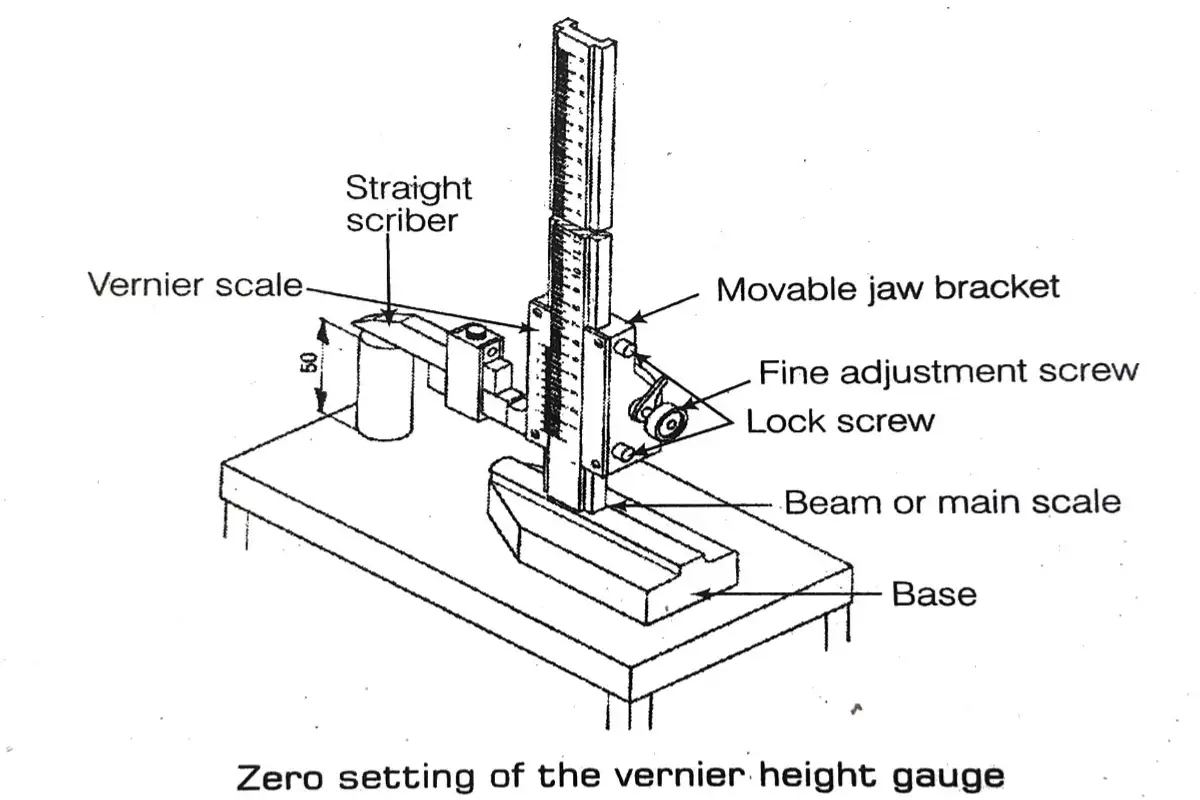
(i) Base
This is the datum with which measurements and settings are made. The lower side of the base is hardened, ground, and lapped.
(ii) Beam
This is similar to the main scale of a vernier caliper and is attached to the base.
Vernier Slide Scriber
This unit’s slides are fixed on the beam and are carried by the vernier plate, locking screws, fine-setting device, and scriber. Some vernier height gauges are provided with a rack and pinion arrangement for moving the slide along the beam.
Vernier height gauges are provided with both straight and offset scribers.
Zero Setting of the Vernier Height Gauge
The offset scriber permits zero setting of the instrument from the datum surface.
While using a straight scriber, the zero setting of the instrument is at a level above the datum surface. In this case, the zero setting is to be checked, and the precision round block is supplied along with the instrument.
Vernier height gauges can be measured from the datum surface, without the special offset scribers are also available.
Size of the Vernier Height Gauge The size of the vernier height gauge is stated by the height of the beam. The beam has 300 mm of height most commonly used size. Vernier height gauges are used on the surface plates or other accurate flat surfaces.
3. Vernier Depth Gauge
A vernier depth gauge is a very commonly used precision instrument for measuring holes, recesses, slots, and steps. Its construction and method of reading are similar to those of a vernier caliper.
Parts of Vernier Depth Gauge
Vernier depth gauge has a base anvil, graduated beam, clamping screw, fine adjustment mechanism, and vernier scale. The base (anvil) is the fixed unit and serves as a datum for measurement. It also carries the vernier scale and the fine adjustment mechanism.
The beam with the main scale graduations is the sliding member or part. Fine adjustments for measurement are made after tightening the clamping screw and the fine adjustment mechanism. While taking measurements, the base should be firmly held against the reference surface.
The relief given at the end of the beam of some vernier depth gauges is used to avoid the seating in the corners of slots and to ensure correct reading.
Precautions while using Vernier Depth Gauge
Remove burrs, if any, before taking measurements. Excessive pressure on the beam, while, taking measurements will lift the base from the reference surface and will show wrong measurement.
4. Micrometer
A micrometer is a precision instrument used to measure a job in the metric system to 0.01 mm and in the British system 0.001 inch or even more than that, as its name itself indicates micro means very smallest and meter means measurement. It works on the principle of screw thread pitch and functions such as nut and bolt so it is also called screw gauge.
The minimum value measured by a micrometer is known as its least count, generally within an accuracy of 0.01 mm.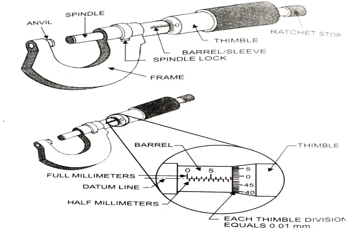
Construction Parts of Micrometer
The parts of a micrometer are given below.
(i) Frame
The frame is made up of drop-forged steel or malleable cast iron. All other parts of the micrometer are attached to this.
(ii) Barrel/Sleeve
The barrel or sleeve is fixed to the frame. The datum line and graduations are marked on this.
(iii) Thimble
On the beveled surface of the thimble, the graduation is also marked and the spindle is attached to it.
(iv) Spindle
One end of the spindle is the measuring face. The other end is threaded and passes through a nut. The threaded mechanism allows for the forward and backward movement of the spindle.
(v) Anvil
The anvil is one of the measuring faces, which is fitted on the micrometer frame. It is made up of alloy steel and finished to a perfectly flat surface.
(vi) Spindle Lock Nut
The spindle lock nut is used to lock the spindle at a desired position.
(vii) Ratchet Stop
The ratchet stop ensures a uniform pressure between the measuring surfaces.
Principle of Micrometer
The micrometer works on the principle of screw and nut. The longitudinal movement of the spindle during one rotation is equal to the pitch of the screw.
The movement of the spindle to the distance of the pitch or its fractions can be accurately measured on the barrel and thimble.
Graduations of Micrometer
In a micrometer, the pitch of the spindle thread is 0.5 mm. Thereby, in one rotation of the thimble, the spindle advances by 0.5 mm. On the barrel, a 25 mm long datum line is marked. This line is further graduated to one millimeter and half one millimeter (i.e., 1 mm and 0.5 mm). The graduations are numbered as 0,5,10,15,20 and 25 mm.
Least Count in Micrometer
A minimum measurement taken by a micrometer is known as the least count.
The least count values of British and Metric micrometers are found in different ways such as follows.
Least Count in Metric Micrometer
In a Metric micrometer, a marking is made on 25 or 50 mm. Inside the sleeve and spindle, put the threads of 1 or 1 / 2 mm. Divide the thimble equally into 100 or 50 parts.
Least count = Spindle distance/number of divisions in thimble
12 / 50 mm = 1 / 100 mm = 0.01 mm
Least Count of British Micrometer
In a British micrometer, one part of the sleeve divides into 10 big divisions and each main division divides into 4 subdivisions. Therefore, 1’= 40 (equally divided)
Value of subdivisions = 1 / 40″ = 0.025″
In one revolution of the thimble = 1 / 40″ = 0.025″
Least count = PitchNumber of divisions in thimble 1 / 40 / 25 = 11000 = 0.001″
Depending on the measurement, some types of micrometers are discussed here.
(i) Outside Micrometer
This micrometer is used to measure the outside diameter of a job and it has a U-shape in which one side head is attached with high carbon steel or tungsten carbide. The tip is called an anvil and the other side of the U-frame consists of the head spindle, sleeve, thimble, etc.
The inner side of the sleeve is made up of threads for the spindle and is attached with a U-frame. The upper part of the micrometer is marked by 1 and 1 by 2 mm.
(ii) Angle Inside Micrometer
The angle inside the micrometer is used to measure the inside dimensions of the job and the minimum measuring range is 2 inches or 50 mm. Its sleeve has a marking of 1 by 2 inches or 10 mm.
If we want to measure the long size of the job, then attach it to the extension rod. Angle inside micrometer, sleeve on the upper side contains thimble. The inside micrometer does not contain a U frame and ratchet. The thimble is available at the place of the ratchet on its upper side, the anvil is also fixed, and another side of the spindle is used to expand the extension bar. There are inside micrometers available in various sizes with measuring ranges from 25 to 50 mm and 50 to 150 mm. The accuracy in reading is 0.01 mm.
The micrometer is placed vertically on the surface of the bore. It needs to be tight at the lower end and turned at the other one until it cannot move anymore. It is first to be removed from the bore and the measurement or readings are to be taken.
Reading A size of 36.38 mm on a metric inside micrometer can be read under
25.00 mm – zero reading of 25 to 50 mm set
10.00 mm – 10 mm extension rod
1.00 mm – 1 main division (1 x 1 mm)
0.50 mm – 1 subdivision
0.18 mm – 18 thimble division (15 x 0.01 mm).
36.88 mm total reading
Zero error must be checked before taking measurements with an inside micrometer.
(ii) Small Inside Micrometer
This micrometer is also used to measure the inside dimensions of a job. It can measure the minimum up to 2″ and 50 mm and the least count is 0.01 mm and 0.001 inch.
(iv) Depth Micrometer
The depth micrometer is a precision measuring instrument used by engineers to measure the depth of jobs. Each revolution of the ratchet moves on the spindle face of 0.5 mm towards the bottom of the blind hole. The diagram below shows how the depth gauge is used.
The ratchet is turned in a clockwise direction until the spindle face touches the bottom of the blind hole. The scales are read in exactly the same way as the scales of a normal micrometer.
The Micrometer sleeve is divided into 10 equal parts. Each part equals 1-tenth of an inch. Each of these is divided into 4 equal parts. Each of these, 4 subdivisions are equal to 0.025 inch.
(v) Screw Thread Micrometer
The screw thread micrometer measures the pitch of the thread directly. The screw thread micrometer has a 60° pointed spindle and a double V-shaped screw thread micrometer indicates the pitch diameter of the thread. When the micrometer is set at zero, the pitch line of the spindle and anvil coincide.
When the micrometer has measuring thread, is used to measure the pitch diameter of the thread along itself.
(vi) Digital Micrometer
Wipe down the object, when you want to measure dimension by the micrometer anvil. Turn the thimble on the micrometer in the clockwise direction. Continue until the contact faces of the anvil and spindle meet each other. Turn the micrometer and push the zero button, if the display reads any number besides zero. Turn the thimble counterclockwise in the direction.
This will raise the spindle and make a gap between the anvil and the spindle. Placed the object on the anvil and below the spindle, until it touches the object. Push the hold button to receive a measurement on the display. Move the spindle on the back side and push the object aside. Turn off the micrometer.
(vii) Vernier Micrometer
To increase the accuracy of the micrometer, we can take the help of an vernier micrometer. In the vernier micrometer, mark the 10 equal lines on the sleeve, which are parallel to the datum lines.
(viii) Combi Micrometer
This is an instrument that is used to measure both metric and English readings at a time by sleeve, thimble, and digital counter. It is of two types as follows.
(a) First Combination
It is used to measure in the Metric and English systems on the digital counter. In this combination, the sleeve and thimble are measured in the metric system, and the digital counter is converted into the English system.
(b) Second Combination
It is similar to the first combination. But, the sleeve and thimble are measured in the English system, and then a digital counter is converted into the Metric system.
(ix) Hub Micrometer
The frame of the hub micrometer is smaller than the general micrometer. So, it is easily fixed inside of a small diameter hole. It is used to measure the dimensions of the pulley, gear, etc. So, it is called a hub micrometer.
(x) Tube Micrometer
The anvil and spindle have measuring faces opposite to each other. This type of micrometer is either spherical or flat-shaped. This type of micrometer is useful for measuring the wall thickness of a specially shaped tube with a non-circular outside diameter.
(xi) Anvil Micrometer
It is used to measure the diameter of a cylindrical and circular job and it has a V shape structure, consisting of always 60° and measuring value by its 2/3rd times. of diameter, so that it provides the accurate value after calculation.
(xii) Sheet Micrometer
It is used to measure the internal thickness of a job. The difference between the static anvil and dynamic anvil is very low, but the depth is very high which helps to inside thickness of any sheet.
(xiii) Blade Type Micrometer
The anvil and non-rotating spindles of this type of micrometer have blades to allow narrow grooves, keyways, and other restricted areas to be measured. They require careful checking, as the small contact area is subjected to wear as the non-rotating spindle against the rotating screw.
(xiv) Flange Micrometer
It is used to measure the accuracy of the gear teeth., it is also called a gear tooth micrometer and is also used for measuring the width of fins, which are marked on a cylinder.
(xv) Three-Point Internal Micrometer
The set of three high precision has three points to measure accurate dimensions of bores. The self-centre measuring head consists of three laterally positioned, carbide anvils offset at 120° intervals. Their design allows these micrometers to measure down to 1.5 mm of the bottom of a blind bore.
Difference between Vernier Caliper and Micrometer
| Vernier Caliper | Micrometer |
| It is used to measure the inner, outer, and depth of a job. | To measure the inner, outer, and depth of a job, separate micrometers are required. |
| Both metric and English measurements can be taken | A separate micrometer is required for each system of measurement. |
| Vernier caliper can measure up to a very big range, i.e., 0 to 300 mm and 0 to 12 inches, etc. | To measure up to 300 mm is required. |
| To read the vernier caliper, many skills are required. | It is easy to read. |
| The lowest count of the vernier caliper in the Metric system is 0.02 mm. | The least count of micrometers in the Metric system is 0.01 mm. |
| Accurate measurement cannot be taken by vernier caliper. | Accurate measurements can be taken by a micrometer. |
5. Vernier Bevel Protractor
A vernier protractor with a magnifying glass for precise reading of angles on a workpiece has features or setting angles on machine tools. It is constructed of hardened stainless steel and has a measuring angle with maximum accuracy.
The bevel protractor is a type of protractor Le., circular in shape and has a pivoted arm used for measuring and marking off angles. This type of protractor is commonly used for architectural and mechanical purposes.
The other types of protractors consist of the basic protractor, circular protractor, and external protractor. The basic protractor is most commonly used in school i.e., in geometry classes for measuring angles up to 180°. The circular protractor is used when measuring angles up to 360°.
An external protractor is used for spheres and is commonly utilized by astronomers, while these types of protractors are useful for basic angle measurements. The bevel protractor will prove to be the most beneficial type in any design or construction project.
Construction of Vernier Bevel Protractor
A bevel protractor has a full circular scale that is made up of 360°. Unlike simpler protractors that only provide degree measurement, a bevel protractor also has a vernier scale.
One vernier is equal to 1/12 of a degree, which provides a more accurate measurement. When drafting a design, it is important, to have precise measurements that will later correspond to the final product.
The main scale on a bevel protractor has four 90° components. The vernier scale is divided into 24 increments with 12 species on either side of the zero.
6. Sine Bar
It is made up of steel and has a rectangular block shape with a matching cylinder on each end that is used for setting workpieces at various angles for the matching or inspection of parts. A sine bar is ground and lapped to a high accuracy.
Construction of a Sine Bar
It is a precision instrument, which is used for accurate setting of angle and checking of taper. A sine bar consists of a hardened precision ground body with two precision ground cylinders fixed at its both ends with a roller screw, which holds it in contact with both faces of the step.
When a sine bar is placed on a level surface, the top edge will be parallel to that surface. If one roller is raised by a known distance, usually using a gauge block, then the top edge of the bar will be fitted by the same amount forming an angle that may be calculated by the sine rule. Sine bar must be ensured that
(a) The rollers must be of the same diameter.
(b) The distance between the centers of the rollers, i.e., 100 or 250 mm must be absolutely correct.
(c) The line passing through the centers of the two rollers must be absolutely parallel with the bottom. and top edges of the bar.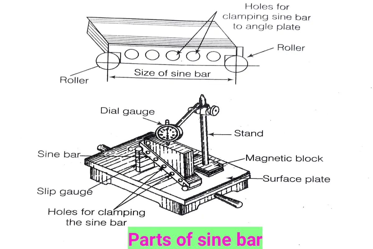
Principle of Sine Bar
The sine bar is based on the principle that
the center distance between the cylinders is employed as the hypotenuse of a right angle, ABC (see figure).
The height BC enables the value of the angle to be calculated from its sine, using the following relationship.
Applications of a Sine Bar
The applications of a sine bar are as follows.
(i) A 100 mm sine bar is supported by a gauge block 20.79 mm high. What is the angle of the sine bar?
The angle of the sine bar, sin = Height of gauge block / 100 = 20.79 / 100
sin 12°= 0.2079, = 12°0′
(ii) A 200 mm sine bar is to be set up at 27°30′. What is the height of the gauge block?
Height of gauge block
= sin x 200 sin 27°30′ x 200
= 0.4617x 200 = 92.34 mm
Optical Flat
Optical flats are made up of glass in different shapes of circular pieces, which is used for checking the flatness and parallelism of the finishing surfaces of instruments such as surfaces of slip gauges, and faces of a micrometer i.e. anvil and spindle.
In an optical flat, there are many lines in a ring. These lines are present in the middle of the surface in a thin layer. The accuracy of an optical flat is measured in the fraction of a reference wavelength of 632 nm. The light waves are reflected from both the bottom surfaces of the flat and the surface. It is a thin film interface occurrence. The reflected waves interface, creating a pattern of interface fringe visible as light and dark bands.
The value obtained by the measuring instruments may have some error due to improper use of the instrument or lack of effort, during the measuring error in measuring value, which also appears due to error in instrument.
To understand the error in measurement, we must be familiar with the technique of using the instruments under different conditions. These techniques and types of errors are discussed here.
Humanistic Errors in Measurement
The knowledge of measuring instruments is used to measure length, breadth, and height. Therefore, some errors are present in measurement. So, the study of these types of errors is necessary. The different types of errors are given below.
1. Geometric Error
When we mark a line on a job, then some errors produce its curved shape. It is of two types, which are as follows.
(i) Micro Geometric Error
On a roughing surface, a measuring instrument cannot take the appropriate value due to its roughness. So, such types of errors are called micro geometric errors.
(ii) Macro Geometric Error
When a cylinder is tapered or out of round, then the macro geometric error takes place. To take the right value, measure the object at different places and find the average value.
2. Contact Error
It generally occurs between the measuring tip and the job. In the contact error, the job is not properly contacted with measuring instruments. Therefore, these errors are created are called contact errors.
3. Systematic Error
The errors, that are generated by measuring instruments, are called systematic errors. These are of two types, which are as follows.
(i) Unknown Systematic Error
This type of error is present due to friction. If one side’s friction is more and the other side less, then measuring values are different.
(ii) Known Systematic Error
This type of error is present due to rubbing of its jaw and backlash. The errors are indicated by their types and their effects so that after measuring, their values are increased or decreased and find appropriate values. Such types of errors are present in the vernier caliper and micrometer.
4. Temperature Error
The errors, that occur due to changes in temperature at the time of measurement, are called temperature errors.
5. Random Error
This type of error is present due to sudden, Differences in temperature, and contemporary reasons. E.g. motion, presence of coldness in air, etc.
6. Cosine Error
If the plunger of an instrument or point is not perpendicular to the job, then such types of errors are called cosine errors.
7. Observer Error
While taking the readings, that time observer must see in front of the object.
8. Instrument and Gauge Error
The errors, which occur, due to improper use of an instrument, are called instrument and gauge errors.
9. Parallel Error
If we measure the breadth of an incline job, then the anvil of the instrument must be circular and pointed, otherwise flat anvil produces some errors.